10.12
Alternating Current versus Direct Current
Chapter contents: Chapter 10: Magnetism
Alternating Current
Most of the examples in electric circuits, and particularly those utilizing batteries, have constant voltage sources. Once the current is established, it is thus also a constant. Direct current (DC) is the flow of electric charge in only one direction. It is the steady state of a constant-voltage circuit. Many well-known applications, however, use a time-varying voltage source. Alternating current (AC) is the flow of electric charge that periodically reverses direction. If the source varies periodically, particularly sinusoidally, the circuit is known as an alternating current circuit. Examples include the commercial and residential power that serves so many of our needs. Figure 10.12.1 shows graphs of voltage and current versus time for typical DC and AC power. The AC voltages and frequencies commonly used in homes and businesses vary around the world. The AC voltages range from 100 V to 240 V; the frequencies range from 50 Hz to 60 Hz.
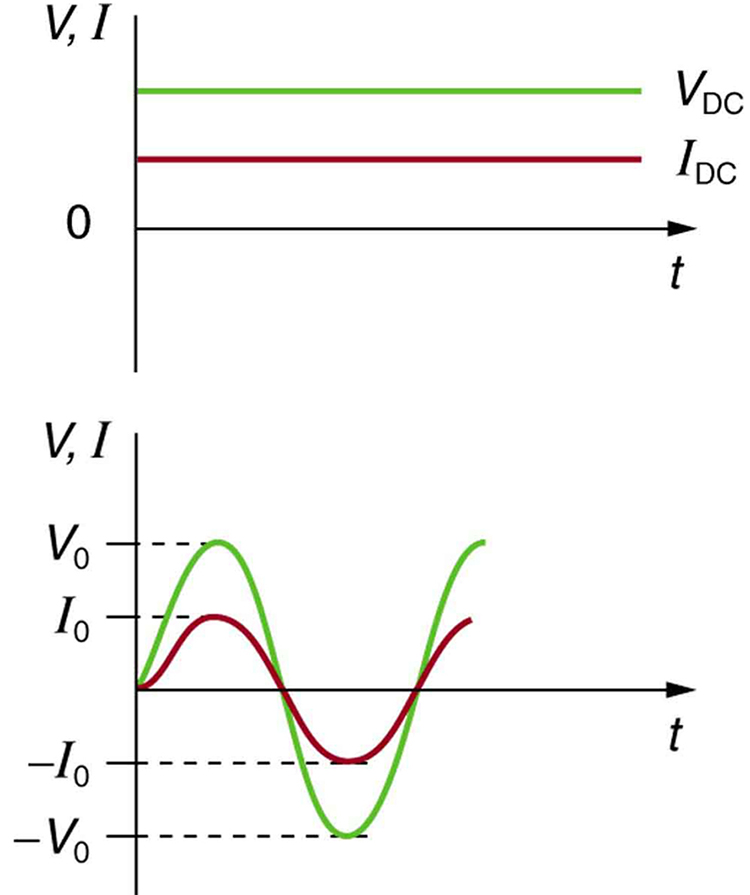
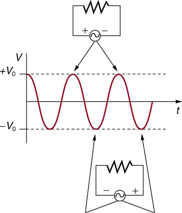
Figure 10.12.2 shows a schematic of a simple circuit with an AC voltage source. The voltage between the terminals fluctuates as shown. For this example, the voltage and current are said to be in phase, as seen in Figure 10.12.1(b).
Current in the resistor alternates back and forth just like the driving voltage, since . If the resistor is a fluorescent light bulb, for example, it brightens and dims 120 times per second as the current repeatedly goes through zero. A 120-Hz flicker is too rapid for your eyes to detect, but if you wave your hand back and forth between your face and a fluorescent light, you will see a stroboscopic effect evidencing AC. The fact that the light output fluctuates means that the power is fluctuating. The power supplied is .
Making Connections: Take-Home Experiment—AC/DC Lights
Wave your hand back and forth between your face and a fluorescent light bulb. Do you observe the same thing with the headlights on your car? Explain what you observe. Warning: Do not look directly at very bright light.
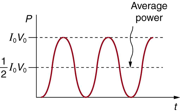
We are most often concerned with average power rather than its fluctuations—that 60-W light bulb in your desk lamp has an average power consumption of 60 W, for example. As illustrated in Figure 10.12.3. One common way to express an average is "root-mean-square," or "rms." For example, rms voltage of an AC voltage source is found by first squaring the voltage ("square"), taking an average of this value over one period of oscillation ("mean"), and taking the square root ("root").
It is standard practice to quote , , and rather than the peak values. For example, most household electricity is 120 V AC, which means that is 120 V. The common 10-A circuit breaker will interrupt a sustained greater than 10 A. Your 1.0-kW microwave oven consumes , and so on. You can think of these rms and average values as the equivalent DC values for a simple resistive circuit.
To summarize, when dealing with AC, Ohm’s law and the equations for power are completely analogous to those for DC, but rms and average values are used for AC. Thus, for AC, Ohm’s law is written
(10.12.1)
The various expressions for AC power are
(10.12.2)
(10.12.3)
and
(10.12.4)
Why Use AC for Power Distribution?
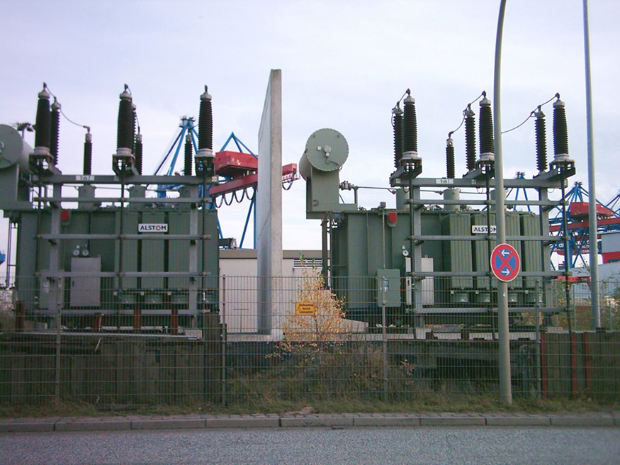
Most large power-distribution systems are AC. Moreover, the power is transmitted at much higher voltages than the 120-V AC (240 V in most parts of the world) we use in homes and on the job. Economies of scale make it cheaper to build a few very large electric power-generation plants than to build numerous small ones. This necessitates sending power long distances, and it is obviously important that energy losses en route be minimized. High voltages can be transmitted with much smaller power losses than low voltages, as we shall show below. (See Figure 10.12.4.) For safety reasons, the voltage at the user is reduced to familiar values. The crucial factor is that AC voltages can be increased and decreased efficiently with transformers (which uses electromagnetic induction to produce time-varying voltages), while it is more difficult to change DC voltages without power losses. So AC is used in most large power distribution systems.
Example 10.12.1
Power Losses Are Less for High-Voltage Transmission
(a) What current is needed to transmit 100 MW of power at 200 kV? (b) What is the power dissipated by the transmission lines if they have a resistance of ? (c) What percentage of the power is lost in the transmission lines?
Strategy
We are given , , and the resistance of the lines is . Using these givens, we can find the current flowing (from ) and then the power dissipated in the lines (), and we take the ratio to the total power transmitted.
Solution
To find the current, we rearrange the relationship and substitute known values. This gives
(10.12.5)
Solution
Knowing the current and given the resistance of the lines, the power dissipated in them is found from . Substituting the known values gives
(10.12.6)
Solution
The percent loss is the ratio of this lost power to the total or input power, multiplied by 100:
(10.12.7)
Discussion
One-fourth of a percent is an acceptable loss. Note that if 100 MW of power had been transmitted at 25 kV, then a current of 4000 A would have been needed. This would result in a power loss in the lines of 16.0 MW, or 16.0% rather than 0.250%. The lower the voltage, the more current is needed, and the greater the power loss in the fixed-resistance transmission lines. Of course, lower-resistance lines can be built, but this requires larger and more expensive wires. If superconducting lines could be economically produced, there would be no loss in the transmission lines at all. But, as we shall see in a later chapter, there is a limit to current in superconductors, too. In short, high voltages are more economical for transmitting power, and AC voltage is much easier to raise and lower, so that AC is used in most large-scale power distribution systems.
Section Summary
- Ohm’s law for AC is .
- Expressions for the average power of an AC circuit are , , and , analogous to the expressions for DC circuits.
Conceptual Questions
Exercise 17
Give an example of a use of AC power other than in the household. Similarly, give an example of a use of DC power other than that supplied by batteries.
Exercise 18
Why do voltage, current, and power go through zero 120 times per second for 60-Hz AC electricity?
Exercise 19
You are riding in a train, gazing into the distance through its window. As close objects streak by, you notice that the nearby fluorescent lights make dashed streaks. Explain.
Problem Exercises
Exercise 43
Military aircraft use 400-Hz AC power, because it is possible to design lighter-weight equipment at this higher frequency. What is the time for one complete cycle of this power?
Solution
2.50 ms
Exercise 44
A North American tourist takes his 25.0-W, 120-V AC razor to Europe, finds a special adapter, and plugs it into 240 V AC. Assuming constant resistance, what power does the razor consume as it is ruined?
Exercise 45
In this problem, you will verify statements made at the end of the power losses for Example 10.12.1. (a) What current is needed to transmit 100 MW of power at a voltage of 25.0 kV? (b) Find the power loss in a transmission line. (c) What percent loss does this represent?
Solution
(a) 4.00 kA
(b) 16.0 MW
(c) 16.0%
Exercise 46
A small office-building air conditioner operates on 408-V AC and consumes 50.0 kW. (a) What is its effective resistance? (b) What is the cost of running the air conditioner during a hot summer month when it is on 8.00 h per day for 30 days and electricity costs ?
Exercise 47
What is the average power consumption of a 120-V AC microwave oven that draws 10.0 A?
Solution
1.20 kW
Exercise 48
What is the average current through a 500-W room heater that operates on 120-V AC power?
Exercise 49
Two different electrical devices have the same power consumption, but one is meant to be operated on 120-V AC and the other on 240-V AC. (a) What is the ratio of their resistances? (b) What is the ratio of their currents? (c) Assuming its resistance is unaffected, by what factor will the power increase if a 120-V AC device is connected to 240-V AC?
Solution
(a) 4.0
(b) 0.50
(c) 4.0
Exercise 50
Nichrome wire is used in some radiative heaters. Find the resistance needed if the average power output is to be 1.00 kW utilizing 120-V AC.
direct current
(DC) the flow of electric charge in only one direction
alternating current
(AC) the flow of electric charge that periodically reverses direction
AC voltage
voltage that fluctuates sinusoidally with time.
AC current
current that fluctuates sinusoidally with time.
rms
a type of average taken for a time-varying quantity by squaring it, taking the mean of the square, and then taking the square-root of the mean.