8.12
Applications of Thermodynamics: Heat Pumps and Refrigerators
Chapter contents: Chapter 8: Thermal Physics
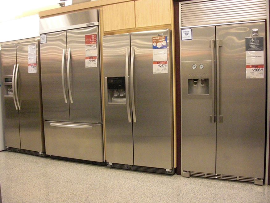
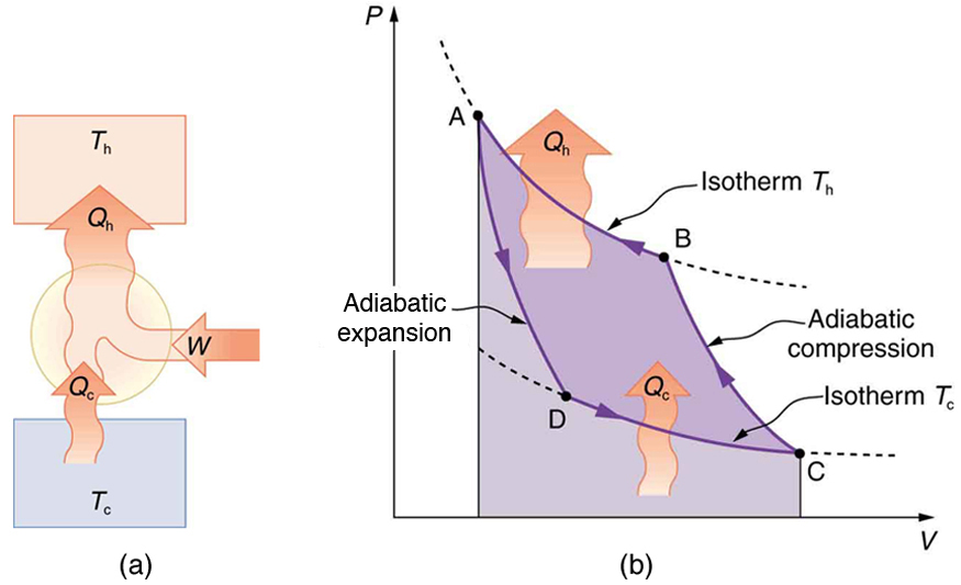
Heat pumps, air conditioners, and refrigerators operate by causing heat transfer from cold to hot. Imagine a heat-engine cycle run backward: the system absorbs heat from a cold reservoir, and work is done on it so that it can release heat into a hot reservoir. Over a complete cycle, the work input adds to the energy released as heat, so the first law gives . (Note that , , and are positive, with their directions indicated on schematics rather than by sign.) A heat pump’s mission is for heat transfer to occur into a warm environment, such as a home in the winter. The mission of air conditioners and refrigerators is for heat transfer to occur from a cool environment, such as chilling a room or keeping food at lower temperatures than the environment. (Actually, a heat pump can be used both to heat and cool a space. It is essentially an air conditioner and a heating unit all in one. In this section we will concentrate on its heating mode.)
Heat Pumps
The great advantage of using a heat pump to keep your home warm, rather than just burning fuel, is that a heat pump supplies . Heat transfer is from the outside air, even at a temperature below freezing, to the indoor space. You only pay for , and you get an additional heat transfer of from the outside at no cost; in many cases, at least twice as much energy is transferred to the heated space as is used to run the heat pump. When you burn fuel to keep warm, you pay for all of it. The disadvantage is that the work input (required by the second law of thermodynamics) is sometimes more expensive than simply burning fuel, especially if the work is done by electrical energy.
The basic components of a heat pump in its heating mode are shown in Figure 8.12.3. A working fluid such as a non-CFC refrigerant is used. In the outdoor coils (the evaporator), heat transfer occurs to the working fluid from the cold outdoor air, turning it into a gas.
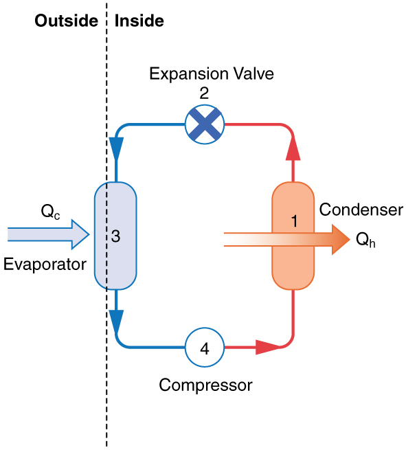
The electrically driven compressor (work input ) raises the temperature and pressure of the gas and forces it into the condenser coils that are inside the heated space. Because the temperature of the gas is higher than the temperature inside the room, heat transfer to the room occurs and the gas condenses to a liquid. The liquid then flows back through a pressure-reducing valve to the outdoor evaporator coils, being cooled through expansion. (To switch to cooling, a reversing valve changes the refrigerant flow so that the indoor coil acts as the evaporator and the outdoor coil acts as the condenser.)
The quality of a heat pump is judged by how much heat transfer occurs into the warm space compared with how much work input is required. In the spirit of taking the ratio of what you get to what you spend, we define a heat pump’s coefficient of performance () to be
.
(8.12.1)For a reversible heat-engine cycle run backward as a heat pump, the efficiency of the forward cycle is , we see that , an important and interesting fact. First, since the efficiency of any heat engine is less than 1, it means that is always greater than 1—that is, a heat pump always has more heat transfer than work put into it. Second, it means that heat pumps work best when temperature differences are small. The efficiency of a perfect, or Carnot, engine is ; thus, the smaller the temperature difference, the smaller the efficiency and the greater the (because ). In other words, heat pumps do not work as well in very cold climates as they do in more moderate climates.
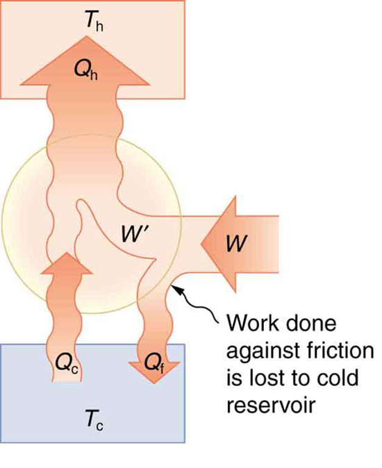
Friction and other irreversible processes reduce heat engine efficiency, but they do not benefit the operation of a heat pump. This is part of what it means for a process to be irreversible. We can model these losses by letting only a portion of the work input reach a reversible heat pump, with the rest dissipated outside the hot reservoir. For the same heat delivery to the hot reservoir at the same reservoir temperatures, greater work input is needed.
Example 8.12.1
The Best COP hp of a Heat Pump for Home Use
A heat pump used to warm a home must employ a cycle that produces a working fluid at temperatures greater than typical indoor temperature so that heat transfer to the inside can take place. Similarly, it must produce a working fluid at temperatures that are colder than the outdoor temperature so that heat transfer occurs from outside. Its hot and cold reservoir temperatures therefore cannot be too close, placing a limit on its . (See Figure 8.12.5.) What is the best coefficient of performance possible for such a heat pump, if it has a hot reservoir temperature of and a cold reservoir temperature of ?
Strategy
A Carnot engine reversed will give the best possible performance as a heat pump. As noted above, , so that we need to first calculate the Carnot efficiency to solve this problem.
Solution
Carnot efficiency in terms of absolute temperature is given by:
.
The temperatures in kelvins are and , so that
.
Thus, from the discussion above,
,
or
,
so that
.
Discussion
This result means that the heat transfer by the heat pump is 5.30 times as much as the work put into it. It would cost 5.30 times as much for the same heat transfer by an electric room heater as it does for that produced by this heat pump. This is not a violation of conservation of energy. Cold ambient air provides 4.3 J per 1 J of work from the electrical outlet.
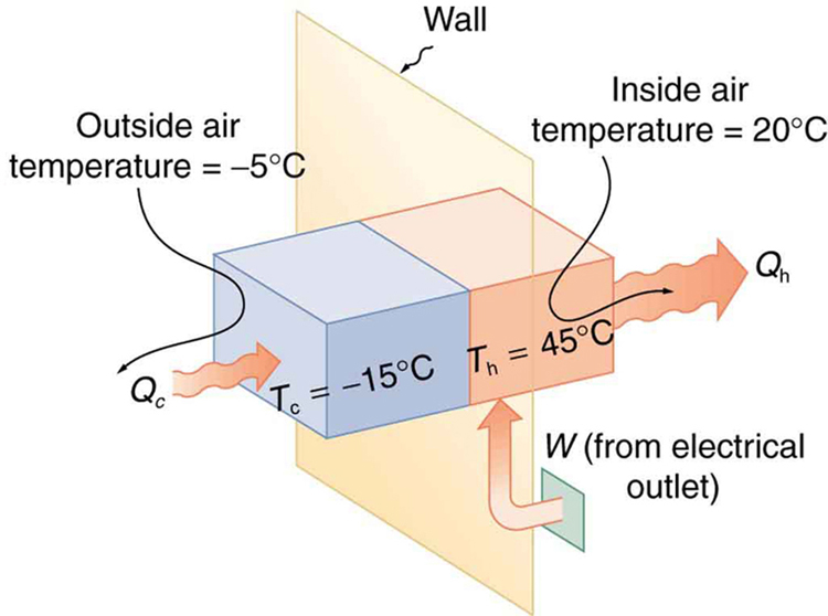
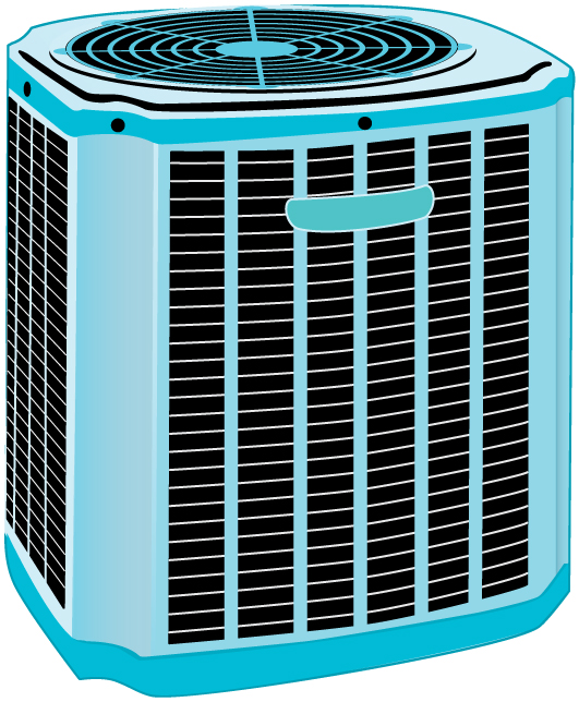
Real heat pumps do not perform quite as well as the ideal one in the previous example; their values of range from about 2 to 4. This range means that the heat transfer from the heat pumps is 2 to 4 times as great as the work put into them. Their economical feasibility is still limited, however, since is usually supplied by electrical energy that costs more per joule than heat transfer by burning fuels like natural gas. Furthermore, the initial cost of a heat pump is greater than that of many furnaces, so that a heat pump must last longer for its cost to be recovered. Heat pumps are most likely to be economically superior where winter temperatures are mild, electricity is relatively cheap, and other fuels are relatively expensive. The mild winters of the San Francisco Bay Area, home to College of Alameda, are well suited to efficient heat-pump heating. Also, since they can cool as well as heat a space, they have advantages where cooling in summer months is also desired. Thus some of the best locations for heat pumps are in warm summer climates with cool winters. Figure 8.12.6 shows a heat pump, called a “reverse cycle” or “split-system cooler” in some countries.
Air Conditioners and Refrigerators
Air conditioners and refrigerators are designed to cool something down in a warm environment. As with heat pumps, work input is required for heat transfer from cold to hot, and this is expensive. The quality of air conditioners and refrigerators is judged by how much heat transfer occurs from a cold environment compared with how much work input is required. What is considered the benefit in a heat pump is considered waste heat in a refrigerator. We thus define the coefficient of performance of an air conditioner or refrigerator to be
.
(8.12.2)Noting again that , we can see that an air conditioner will have a lower coefficient of performance than a heat pump, because and is greater than . In this module’s Problems and Exercises, you will show that
for a heat engine used as either an air conditioner or a heat pump operating between the same two temperatures. Real air conditioners and refrigerators typically do remarkably well, having values of ranging from 2 to 6. These numbers are better than the values for the heat pumps mentioned above, because the temperature differences are smaller, but they are less than those for Carnot engines operating between the same two temperatures.
A type of rating system called the “energy efficiency rating” () has been developed. This rating is an example where non-SI units are still used and relevant to consumers. To make it easier for the consumer, Australia, Canada, New Zealand, and the U.S. use an Energy Star Rating out of 5 stars—the more stars, the more energy efficient the appliance. are expressed in mixed units of British thermal units (Btu) per hour of heating or cooling divided by the power input in watts. Room air conditioners are readily available with ranging from 6 to 12. Although not the same as the just described, these are good for comparison purposes—the greater the , the cheaper an air conditioner is to operate (but the higher its purchase price is likely to be).
The of an air conditioner or refrigerator can be expressed as
,
(8.12.4)where
is the amount of heat transfer from a cold environment in British thermal units,
is time in hours,
is the work input in joules, and
is time in seconds.