10.8
Magnetic Fields Produced by Currents: Ampere’s Law
Chapter contents: Chapter 10: Magnetism
How much current is needed to produce a significant magnetic field, perhaps as strong as the Earth’s field? Surveyors will tell you that overhead electric power lines create magnetic fields that interfere with their compass readings. Indeed, when Oersted discovered in 1820 that a current in a wire affected a compass needle, he was not dealing with extremely large currents. How does the shape of wires carrying current affect the shape of the magnetic field created? We noted earlier that a current loop created a magnetic field similar to that of a bar magnet, but what about a straight wire or a toroid (doughnut)? How is the direction of a current-created field related to the direction of the current? Answers to these questions are explored in this section, together with a brief discussion of the law governing the fields created by currents.
Magnetic Field Created by a Long Straight Current-Carrying Wire: Right Hand Rule 2
Magnetic fields have both direction and magnitude. As noted before, one way to explore the direction of a magnetic field is with compasses, as shown for a long straight current-carrying wire in Figure 10.8.1. Hall probes can determine the magnitude of the field. The field around a long straight wire is found to be in circular loops. The right hand rule 2 (RHR-2) emerges from this exploration and is valid for any current segment—point the thumb in the direction of the current, and the fingers curl in the direction of the magnetic field loops created by it.
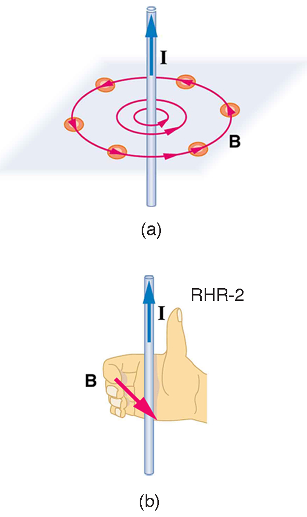
The magnetic field strength (magnitude) produced by a long straight current-carrying wire is found by experiment to be
(long straight wire),
(10.8.1)where is the current, is the shortest distance to the wire, and the constant is the permeability of free space.
is one of the basic constants in nature. We will see later that is related to the speed of light.) Since the wire is very long, the magnitude of the field depends only on distance from the wire , not on position along the wire. The displayed numerical value is an approximation; in the current SI this constant is determined experimentally.
Example 10.8.1
Calculating Current that Produces a Magnetic Field
Find the current in a long straight wire that would produce a magnetic field twice the strength of the Earth’s at a distance of 5.0 cm from the wire.
Strategy
The Earth’s field is about , and so here due to the wire is taken to be . The equation can be used to find
, since all other quantities are known.
Solution
Solving for and entering known values gives
.
Discussion
So a moderately large current produces a significant magnetic field at a distance of 5.0 cm from a long straight wire. Note that the answer is stated to only two digits, since the Earth’s field is specified to only two digits in this example.
Ampere’s Law and Others
Each small segment of a steady current contributes to the magnetic field. The Biot-Savart law gives the size and direction of that contribution; adding the contributions from all segments gives the total field. Ampere’s law provides another relationship: for steady currents, the accumulated component of the magnetic field along a closed path is proportional to the net current passing through a surface bounded by that path. This is especially useful for highly symmetric current arrangements. Maxwell later extended this law to include changing electric fields, as discussed in Maxwell’s Equations: Electromagnetic Waves Predicted and Observed.
Magnetic Field Produced by a Current-Carrying Circular Loop
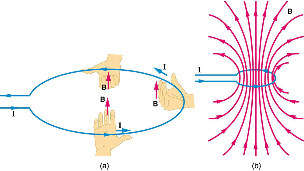
The magnetic field near a current-carrying loop of wire is shown in Figure 10.8.2. Both the direction and the magnitude of the magnetic field produced by a current-carrying loop are complex. RHR-2 can be used to give the direction of the field near the loop, but mapping with compasses and the rules about field lines given in “Magnetic Fields and Magnetic Field Lines” are needed for more detail. There is a simple formula for the magnetic field strength at the center of a circular loop. It is
(at center of loop),
(10.8.2)where is the radius of the loop. This equation is very similar to that for a straight wire, but it is valid only at the center of a circular loop of wire. The similarity of the equations does indicate that similar field strength can be obtained at the center of a loop. One way to get a larger field is to have loops; then, the field is . Note that the larger the loop, the smaller the field at its center, because the current is farther away.
Magnetic Field Produced by a Current-Carrying Solenoid
A solenoid is a long coil of wire (with many turns or loops, as opposed to a flat loop). Because of its shape, the field inside a solenoid can be very uniform, and also very strong. The field just outside the coils is nearly zero. Figure 10.8.3 shows how the field looks and how its direction is given by RHR-2.
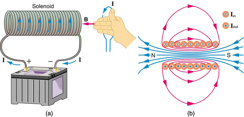
The magnetic field inside of a current-carrying solenoid is very uniform in direction and magnitude. Only near the ends does it begin to weaken and change direction. The field outside has similar complexities to flat loops and bar magnets, but the magnetic field strength inside a solenoid is simply
(inside a solenoid),
(10.8.3)where is the number of loops per unit length of the solenoid (, with being the number of loops and the length). Note that is the field strength anywhere in the uniform region of the interior and not just at the center. Large uniform fields spread over a large volume are possible with solenoids, as Example 10.8.2 implies.
Example 10.8.2
Calculating Field Strength inside a Solenoid
What is the field inside a 2.00-m-long solenoid that has 2000 loops and carries a 1600-A current?
Strategy
To find the field strength inside a solenoid, we use . First, we note the number of loops per unit length is
.
Solution
Substituting known values gives
.
Discussion
This is a large field strength that could be established over a large-diameter solenoid, such as in medical uses of magnetic resonance imaging (MRI). The very large current is an indication that the fields of this strength are not easily achieved, however. Such a large current through 1000 loops squeezed into a meter’s length would produce significant heating. Higher currents can be achieved by using superconducting wires, although this is expensive. There is an upper limit to the current, since the superconducting state is disrupted by very large magnetic fields.
There are interesting variations of the flat coil and solenoid. A toroid is much like a solenoid bent into a circle, with magnetic field lines forming closed loops inside it. Tokamaks use magnetic fields around a ring-shaped chamber to help confine charged particles for fusion. The particles spiral around magnetic field lines while moving along them. A simple toroidal field does not provide complete confinement: particles can drift across the field, so tokamaks combine magnetic fields in different directions to improve confinement. A whole range of coil shapes are used to produce different magnetic field shapes. Adding ferromagnetic materials can strengthen and reshape the field. These materials can also redirect magnetic fields around a protected region and are used as shields for devices sensitive to external magnetic fields, including Earth’s magnetic field.