10.11
Transformers
Chapter contents: Chapter 10: Magnetism
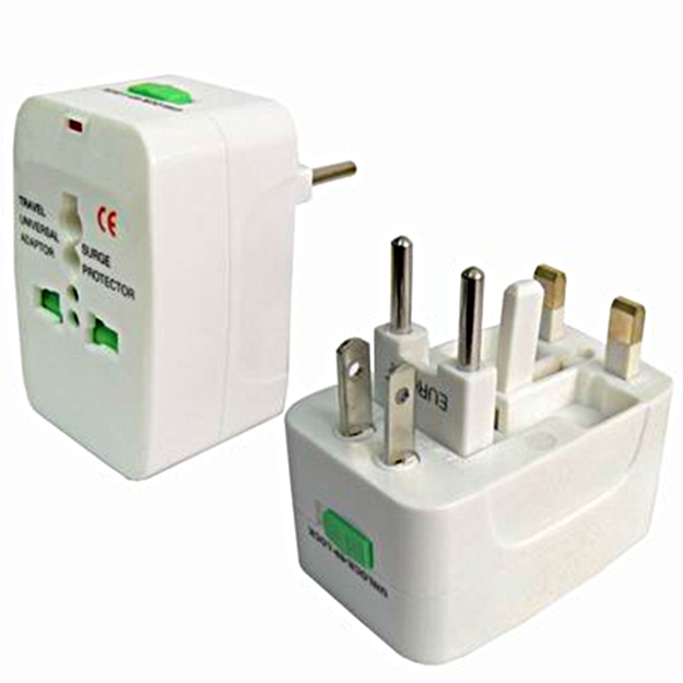
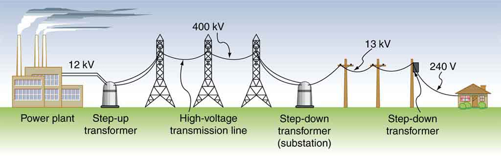
Transformers do what their name implies—they transform voltages from one value to another. For example, many cell phones, laptops, video games, and power tools and small appliances have a transformer built into their plug-in unit (like that in Figure 10.11.1) that changes 120 V or 240 V AC into whatever voltage the device uses. Transformers are also used at several points in the power distribution systems, such as illustrated in Figure 10.11.2. Power is sent long distances at high voltages, because less current is required for a given amount of power, and this means less line loss, as was discussed previously. But high voltages pose greater hazards, so that transformers are employed to produce lower voltage at the user’s location.
The type of transformer considered in this text—see Figure 10.11.3—is based on Faraday’s law of induction and is very similar in construction to the apparatus Faraday used to demonstrate magnetic fields could cause currents. The two coils are called the primary and secondary coils. In normal use, the input voltage is placed on the primary, and the secondary produces the transformed output voltage. Not only does the iron core trap the magnetic field created by the primary coil, its magnetization increases the field strength. Since the input voltage is AC, a time-varying magnetic flux is sent to the secondary, inducing its AC output voltage.
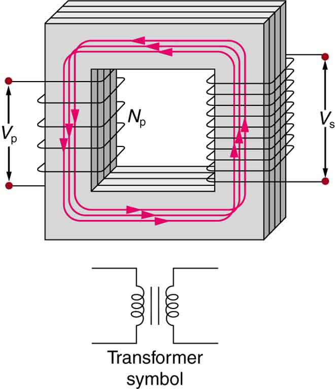
For the simple transformer shown in Figure 10.11.3, the output voltage depends almost entirely on the input voltage and the ratio of the number of loops in the primary and secondary coils. Faraday’s law of induction for the secondary coil gives its induced output voltage to be
(10.11.1)
where is the number of loops in the secondary coil and / is the rate of change of magnetic flux.
The cross-sectional area of the coils is the same on either side, as is the magnetic field strength, and so
is the same on either side. The input primary voltage is also related to changing flux by
(10.11.2)
The reason for this is a little more subtle. Lenz’s law tells us that the primary coil opposes the change in flux caused by the input voltage , hence the minus sign. Assuming negligible coil resistance, Kirchhoff’s loop rule tells us that the induced voltage exactly equals the input voltage. Taking the ratio of these last two equations yields a useful relationship:
(10.11.3)
This is known as the transformer equation, and it simply states that the ratio of the secondary to primary voltages in a transformer equals the ratio of the number of loops in their coils.
The output voltage of a transformer can be less than, greater than, or equal to the input voltage, depending on the ratio of the number of loops in their coils. Some transformers even provide a variable output by allowing connection to be made at different points on the secondary coil. A step-up transformer is one that increases voltage, whereas a step-down transformer decreases voltage. Assuming, as we have, that resistance is negligible, the electrical power output of a transformer equals its input. This is nearly true in practice—transformer efficiency often exceeds 99%. Equating the power input and output,
(10.11.4)
Rearranging terms gives
(10.11.5)
Combining this with , we find that
is the relationship between the output and input currents of a transformer. So if voltage increases, current decreases. Conversely, if voltage decreases, current increases.
Example 10.11.1
Calculating Characteristics of a Step-Up Transformer
A portable x-ray unit has a step-up transformer, the 120 V input of which is transformed to the 100 kV output needed by the x-ray tube. The primary has 50 loops and draws a current of 10.00 A when in use. (a) What is the number of loops in the secondary? (b) Find the current output of the secondary.
Strategy and Solution for (a)
We solve for , the number of loops in the secondary, and enter the known values. This gives
(10.11.7)
Discussion for (a)
A large number of loops in the secondary (compared with the primary) is required to produce such a large voltage. This would be true for neon sign transformers and those supplying high voltage inside TVs and CRTs.
Strategy and Solution for (b)
We can similarly find the output current of the secondary by solving for and entering known values. This gives
(10.11.8)
Discussion for (b)
As expected, the current output is significantly less than the input. In certain spectacular demonstrations, very large voltages are used to produce long arcs, but they are relatively safe because the transformer output does not supply a large current. Note that the power input here is . This equals the power output , as we assumed in the derivation of the equations used.
Example 10.11.2
Calculating Characteristics of a Step-Down Transformer
A battery charger meant for a series connection of ten nickel-cadmium batteries needs to have a 15.0 V output to charge the batteries. It uses a step-down transformer with a 200-loop primary and a 120 V input. (a) How many loops should there be in the secondary coil? (b) If the charging current is 16.0 A, what is the input current?
Strategy and Solution for (a)
You would expect the secondary to have a small number of loops. Solving for and entering known values gives
(10.11.9)
Strategy and Solution for (b)
The current input can be obtained by solving for and entering known values. This gives
(10.11.10)
Discussion
The number of loops in the secondary is small, as expected for a step-down transformer. We also see that a small input current produces a larger output current in a step-down transformer. When transformers are used to operate large magnets, they sometimes have a small number of very heavy loops in the secondary. This allows the secondary to have low internal resistance and produce large currents. Note again that this solution is based on the assumption of 100% efficiency—or power out equals power in ()—reasonable for good transformers. In this case the primary and secondary power is 240 W. (Verify this for yourself as a consistency check.) Note that the Ni-Cd batteries need to be charged from a DC power source (as would a 12 V battery). So the AC output of the secondary coil needs to be converted into DC. This is done using something called a rectifier, which uses devices called diodes that allow only a one-way flow of current.
Section Summary
- Transformers use induction to transform voltages from one value to another.
- For a transformer, the voltages across the primary and secondary coils are related by
where and are the voltages across primary and secondary coils having and turns.(10.11.11)
- The currents and in the primary and secondary coils are related by .
- A step-up transformer increases voltage and decreases current, whereas a step-down transformer decreases voltage and increases current.
Problems & Exercises
Exercise 35
A plug-in transformer supplies 9.00 V to a video game system. (a) How many turns are in its secondary coil, if its input voltage is 120 V and the primary coil has 400 turns? (b) What is its input current when its output is 1.30 A?
Solution
(a) 30.0
(b)
Exercise 36
An American traveler in New Zealand carries a transformer to convert New Zealand’s standard 240 V to 120 V so that she can use some small appliances on her trip. (a) What is the ratio of turns in the primary and secondary coils of her transformer? (b) What is the ratio of input to output current? (c) How could a New Zealander traveling in the United States use this same transformer to power her 240 V appliances from 120 V?
Exercise 37
A digital recorder uses a plug-in transformer to convert 120 V to 12.0 V, with a maximum current output of 200 mA. (a) What is the current input? (b) What is the power input? (c) Is this amount of power reasonable for a small appliance?
Solution
(a) 20.0 mA
(b) 2.40 W
(c) Yes, this amount of power is quite reasonable for a small appliance.
Exercise 38
(a) What is the voltage output of a transformer used for rechargeable flashlight batteries, if its primary has 500 turns, its secondary 4 turns, and the input voltage is 120 V? (b) What input current is required to produce a 4.00 A output? (c) What is the power input?
Exercise 39
(a) The plug-in transformer for a laptop computer puts out 7.50 V and can supply a maximum current of 2.00 A. What is the maximum input current if the input voltage is 240 V? Assume 100% efficiency. (b) If the actual efficiency is less than 100%, would the input current need to be greater or smaller? Explain.
Solution
(a) 0.063 A
(b) Greater input current needed.
Exercise 40
A multipurpose transformer has a secondary coil with several points at which a voltage can be extracted, giving outputs of 5.60, 12.0, and 480 V. (a) The input voltage is 240 V to a primary coil of 280 turns. What are the numbers of turns in the parts of the secondary used to produce the output voltages? (b) If the maximum input current is 5.00 A, what are the maximum output currents (each used alone)?
Exercise 41
A large power plant generates electricity at 12.0 kV. Its old transformer once converted the voltage to 335 kV. The secondary of this transformer is being replaced so that its output can be 750 kV for more efficient cross-country transmission on upgraded transmission lines. (a) What is the ratio of turns in the new secondary compared with the old secondary? (b) What is the ratio of new current output to old output (at 335 kV) for the same power? (c) If the upgraded transmission lines have the same resistance, what is the ratio of new line power loss to old?
Solution
(a) 2.2
(b) 0.45
(c) 0.20, or 20.0%
Exercise 42
If the power output in the previous problem is 1000 MW and line resistance is , what were the old and new line losses?
transformer
a device that transforms voltages from one value to another using induction
transformer equation
the equation showing that the ratio of the secondary to primary voltages in a transformer equals the ratio of the number of loops in their coils;
step-up transformer
a transformer that increases voltage
step-down transformer
a transformer that decreases voltage