10.6
Magnetic Force on a Current-Carrying Conductor
Chapter contents: Chapter 10: Magnetism
Because charges ordinarily cannot escape a conductor, the magnetic force on charges moving in a conductor is transmitted to the conductor itself.
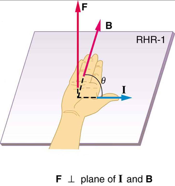
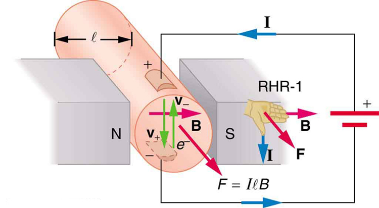
The maximum force on a current-carrying conductor occurs when the current direction and the magnetic field's direction are perpendicular to one another (i.e. ninety degree angle between directions). We can derive an expression for the maximum magnetic force on a current by taking a sum of the magnetic forces on individual charges. (The forces add because they are in the same direction.) The force on an individual charge moving at the drift velocity vd is given by . Taking B to be uniform over a length of wire and zero elsewhere, the total magnetic force on the wire is then , where is the number of charge carriers in the section of wire of length l. Now, , where is the number of charge carriers per unit volume and is the volume of wire in the field. Noting that , where is the cross-sectional area of the wire, then the force on the wire is . Gathering terms,
(10.6.1)
Because ,
(10.6.2)
is the equation for maximum magnetic force on a length of wire carrying a current in a uniform magnetic field , as shown in Figure 10.6.2.
If we divide both sides of this expression by , we find that the magnetic force per unit length of wire in a uniform field is
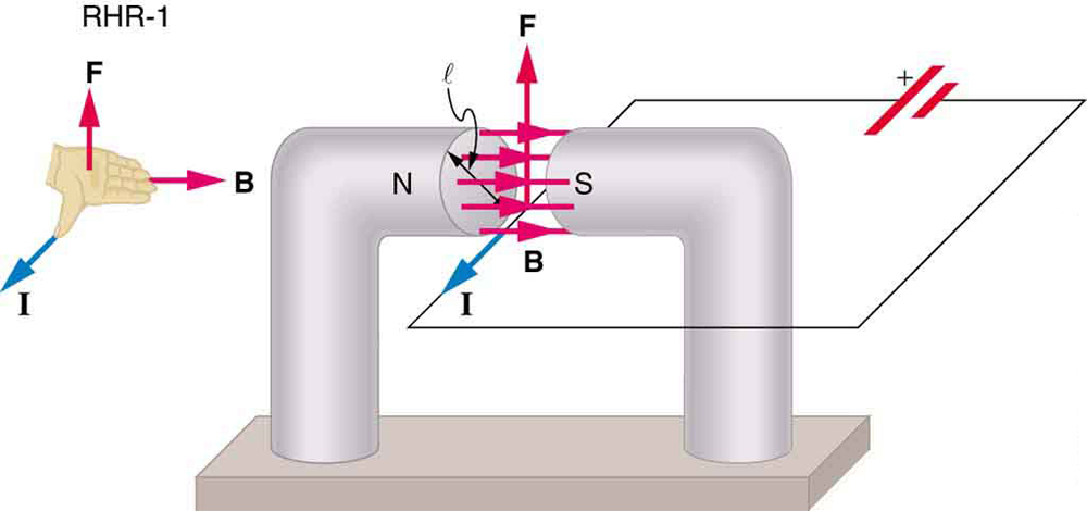
The direction of this force is given by RHR-1, with the thumb in the direction of the current . Then, with the fingers in the direction of , a perpendicular to the palm points in the direction of , as in Figure 10.6.2.
Example 10.6.1
Calculating Magnetic Force on a Current-Carrying Wire: A Strong Magnetic Field
Calculate the force on the wire shown in Figure 10.6.1, given , , and .
Strategy
The force can be found with the given information by using because the angle between and is 90.
Solution
Entering the given values into
yields
(10.6.3)
The units for tesla are ; thus,
(10.6.4)
Discussion
This large magnetic field creates a significant force on a small length of wire.
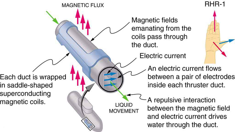
Magnetic force on current-carrying conductors is used to convert electric energy to work. (Motors are a prime example—they employ loops of wire and are considered in the next section.) Magnetohydrodynamics (MHD) is the technical name given to a clever application where magnetic force pumps fluids without moving mechanical parts. (See Figure 10.6.3.)
A strong magnetic field is applied across a tube and a current is passed through the fluid at right angles to the field, resulting in a force on the fluid parallel to the tube axis as shown. The absence of moving parts makes this attractive for moving a hot, chemically active substance, such as the liquid sodium employed in some nuclear reactors. Experimental artificial hearts are testing with this technique for pumping blood, perhaps circumventing the adverse effects of mechanical pumps. (Cell membranes, however, are affected by the large fields needed in MHD, delaying its practical application in humans.) MHD propulsion for nuclear submarines has been proposed, because it could be considerably quieter than conventional propeller drives. The deterrent value of nuclear submarines is based on their ability to hide and survive a first or second nuclear strike. As we slowly disassemble our nuclear weapons arsenals, the submarine branch will be the last to be decommissioned because of this ability (See Figure 10.6.4.) Existing MHD drives are heavy and inefficient—much development work is needed.
Section Summary
- The magnetic force on current-carrying conductors (when current direction and magnetic field direction are perpendicular) is given by
where is the current, is the length of a straight conductor in a uniform magnetic field , and . The force follows RHR-1 with the thumb in the direction of .(10.6.5)
Conceptual Questions
Exercise 7
Draw a sketch of the situation in Figure 10.6.1 showing the direction of electrons carrying the current, and use RHR-1 to verify the direction of the force on the wire.
Exercise 8
Verify that the direction of the force in an MHD drive, such as that in Figure 10.6.3, does not depend on the sign of the charges carrying the current across the fluid.
Exercise 9
Why would a magnetohydrodynamic drive work better in ocean water than in fresh water? Also, why would superconducting magnets be desirable?
Exercise 10
Which is more likely to interfere with compass readings, AC current in your refrigerator or DC current when you start your car? Explain.
Problems & Exercises
Exercise 28
What is the direction of the magnetic force on the current in each of the six cases in Figure 10.E.5? Note that indicates "coming out of the page" and means "going into the page."
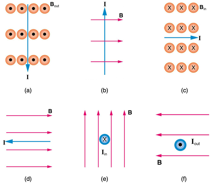
Solution
(a) west (left)
(b) into page
(c) north (up)
(d) no force
(e) east (right)
(f) south (down)
Exercise 29
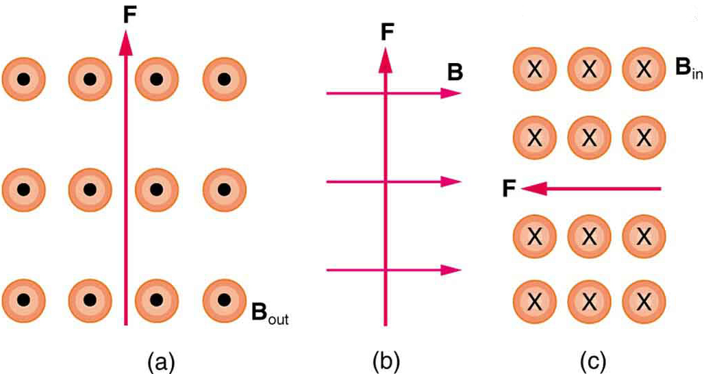
What is the direction of a current that experiences the magnetic force shown in each of the three cases in Figure 10.E.6, assuming the current runs perpendicular to ? Note that indicates "coming out of the page" and means "going into the page."
Exercise 30
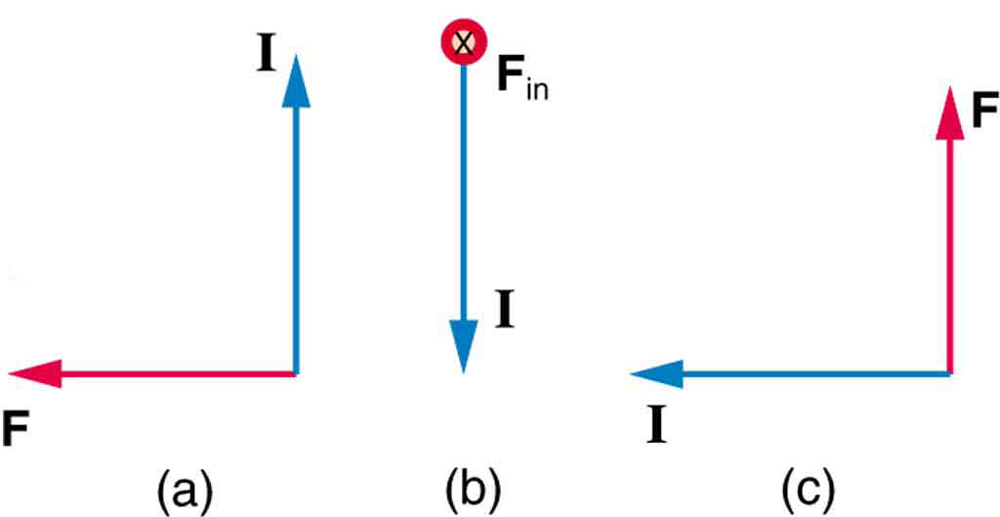
What is the direction of the magnetic field that produces the magnetic force shown on the currents in each of the three cases in Figure 10.E.7, assuming is perpendicular to ? Note that means "going into the page."
Solution
(a) into page
(b) west (left)
(c) out of page
Exercise 31
(a) What is the force per meter on a lightning bolt at the equator that carries 20,000 A perpendicular to the Earth’s field? (b) What is the direction of the force if the current is straight up and the Earth’s field direction is due north, parallel to the ground?
Exercise 32
(a) A DC power line for a light-rail system carries 1000 A.
If Earth’s magnetic field at this location is T, what is the maximum possible magnetic force on a 100-m section of this line? (b) Discuss practical concerns this presents, if any.
Solution
(a) 5.00 N
(b) This is about a pound of force per 100 m of wire, which is much less than the weight of the wire itself. Therefore, it does not cause any special concerns.
Exercise 33
What force is exerted on the water in an MHD drive utilizing a 25.0-cm-diameter tube, if 100-A current is passed across the tube that is perpendicular to a 2.00-T magnetic field? (The relatively small size of this force indicates the need for very large currents and magnetic fields to make practical MHD drives.)
Exercise 34
A wire carrying a 30.0-A current passes between the poles of a strong magnet that is perpendicular to its field and experiences a 2.16-N force on the 4.00 cm of wire in the field. What is the average field strength?
Solution
1.80 T